Final Report on the Collapse of World Trade Center Building
Final Report on the Collapse of World Trade Center Building 7
by NIST National Institute of Standards and Technology
U.S. Department of Commerce, Carlos M. Gutierrez, Secretary
National Institute of Standards and Technology, Patric D. Gallagher, Deputy Director
NIST NCSTAR 1A: Federal Building and Fire Safety Investigation of the World Trade Center Disaster
November, 2008
NOTICE: THIS WORK MAY BE PROTECTED BY COPYRIGHT
Keywords: building evacuation, emergency response, fire safety, structural collapse, tall buildings, World Trade Center.
TABLE OF CONTENTS:
• National Construction Safety Team for the Federal Building and Fire Safety Investigation of the World Trade Center Disaster
• Contributors to the Investigation of WTC 7
• Dedication
• Abstract
• Table of Contents
• List of Figures
• List of Tables
• List of Acronyms and Abbreviations
• Preface
• Executive Summary
• Chapter 1: The New York City World Trade Center Building 7
• 1.1 The World Trade Center Complex
• 1.2 WTC 7
• 1.2.1 The Edifice
• 1.2.2 The Con Edison Substation
• 1.2.3 The Structure
• 1.2.4 Fire Protection
• 1.2.5 The Workplace
• 1.2.6 The Combustible Contents
• 1.3 References
• Chapter 2: The Account of WTC 7
• 2.1 Introduction
• 2.2 Activity at the WTC 7 Site
• 2.2.1 8:46 a.m. to 9:59 a.m. EDT
• 2.2.2 9:59 a.m. to 10:28 a.m. EDT
• 2.2.3 10:29 a.m. to 5:21 p.m. EDT.
• 2.3 Progress of the Fires in WTC 7
• 2.4 The Probable Collapse Sequence
• Chapter 3
• Deriving The Probable Collapse Sequence
• 3.1 Gathering of Evidence
• 3.2 The Leading Hypothesis
• 3.3 Hypothetical Blast Scenarios
• 3.4 The Four-step Simulation Process
• 3.4.1 Technical Approach
• 3.4.2 Fires Simulated
• 3.4.3 Fire Dynamics Simulator (FDS)
• 3.4.4 Fire Structure Interface (FSI)
• 3.4.5 Structural Analysis of the Initial Failure Event using ANSYS
• 3.4.6 Global Collapse Analysis using LS-DYNA
• 3.5 Accuracy of the Probable Collapse Sequence
• 3.5.1 Aspects prior to the Global Collapse
• 3.5.2 Aspects following the Global Collapse Initiation
• 3.5.3 Accuracy Appraisal
• 3.6 Timing of Collapse Initiation and Progression
• 3.7 References
• Chapter 4: Principal Findings
• 4. 1 Introduction
• 4.2 Summary
• 4.3 The Mechanisms of Building Collapse
• 4. 3.1 Debris Impact Damage from the Collapse of WTC 1
• 4.3.2 Reconstruction of the Fires
• 4.3.3 Fire-induced Thermal Effects
• 4.3.4 Structural Response and Collapse
• 4.4 Life Safety Factors
• 4.4.1 Evacuation of WTC 7
• 4.4.2 Emergency Response
• 4.5 Codes. Standards, and Practices
• 4.5.1 General
• 4.5.2 Building Design and Structural Safety
• 4.5.3 SFRM Requirements and Application
• 4.5.4 Fire Safety and Fire Protection Systems
• 4.6 Future Factors That Could Have Mitigated Structural Collapse
• 4.7 Human Performance Factors
• Chapter 5: Recommendations
• 5.1 General
• 5.2 NIST's Recommendations for Improving the Safety of Buildings, Occupants, and Emergency Responders
• 5.2.1 Group 1. Increased Structural Integrity
• 5.2.2 Group 2. Enhanced Fire Endurance of Structures
• 5.2.3 Group 3. New Methods for Fire Resistant Design of Structures
• 5.2.4 Group 4. Improved Active Fire Protection
• 5.2.5 Group 6. Improved Emergency Response 5.2.6 Group 7. Improved Procedures and Practices 5.2.7 Group 8. Education and Training
• Appendix A: National Construction Safety Team Act
• Appendix B: World Trade Center Investigation Publications
LIST OF FIGURES
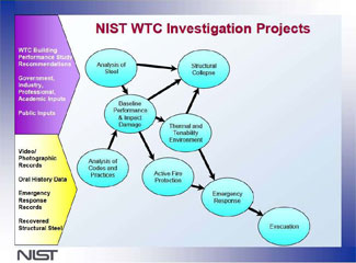
• Figure P-l. Technical components of the Federal Building and Fire Safety Investigation of the WTC Disaster
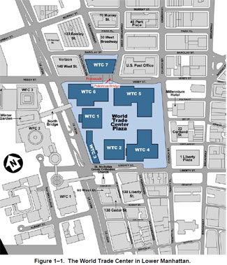
• Figure 1-1. The World Trade Center in Lower Manhattan
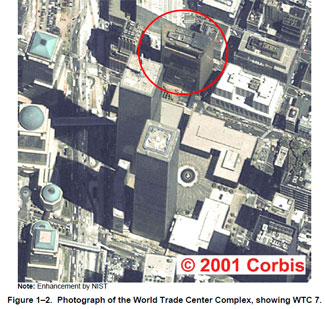
• Figure 1-2. Photograph of the World Trade Center Complex, showing WTC 7
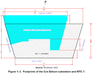
• Figure 1-3. Footprints of the Con Edison substation and WTC 7
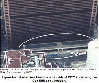
• Figure 1-4. Aerial view from the north side of WTC 7, showing the Con Edison substation
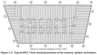
• Figure 1-5. Typical WTC 7 floor showing locations of the columns, girders, and beams
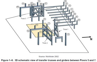
• Figure 1-6. 3D schematic view of transfer trusses and girders between Floors 5 and 7
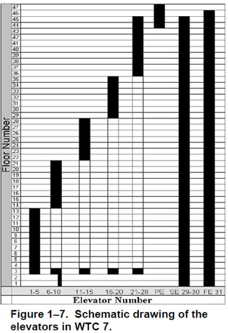
• Figure 1-7. Schematic drawing of the elevators in WTC 7
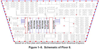
• Figure 1-8. Schematic of Floor 8
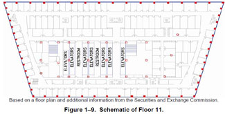
• Figure 1-9. Schematic of Floor 11
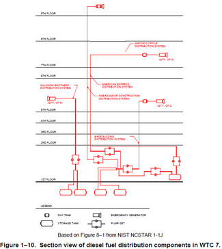
• Figure 1-10. Section view of diesel firel distribution components in WTC 7
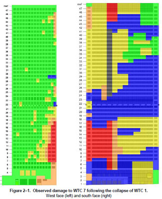
• Figure 2-1. Observed damage to WTC 7 following the collapse of WTC 1
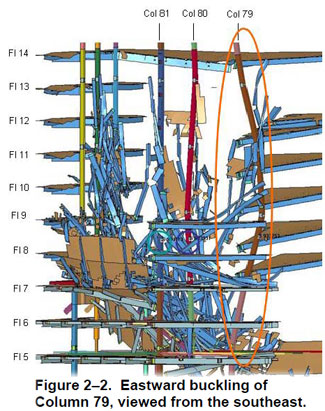
• Figure 2- 2. Eastward buckling of Column 79, viewed from the southeast
• Figure 3- 1. Peak overpressure and broken window locations
• Figure 3- 2. WTC 7 analysis sequence and interdependencies
• Figure 3- 3. Schematic of the layout of the 6th floor of WTC 7
• Figure 3-4. Schematic layout of the 5th floor of WTC 7 showing the locations of the emergency power system components
• Figure 3- 5. Progression of simulated fire on Floor 8 of WTC 7 showing gas temperatures near the ceiling
• Figure 3-6. Progression of simulated fire on Floor 12 of WTC 7 showing gas temperatures near the ceiling
• Figure 3- 7. Computed temperature distribution (DC) of Floor 13 steel framing at five different instants in time
• Figure 3- 8. Computed temperature distribution (DC) in the top layer of the concrete slab of Floor 12 at five different instants in time
• Figure 3- 9. Damage state of connections in Floor 13 for Case B temperatures
• Figure 3- 10. Vertical progression of failures on the east side of the building at 0.5 s following the initiation of the collapse
• Figure 3-11. Failure of Columns 77 and 78 due to failure of Truss 2 fails from debris impact at 2.5 s following the initiation of the collapse
• Figure 3-12. Failure of Columns 73 to 75 from the load redistribution and debris impact at 4.5 s following the initiation of the collapse
• Figure 3-13. Buckling of all interior columns at 6.5 s following the initiation of the collapse
• Figure 3-14. Buckling of the lower exterior columns within 1 s of Figure 3-13
• Figure 3-15. Downward velocity of north face roofline as WTC 7 began to collapse
LIST OF TABLES
• Table P- l. Federal Building and Fire Safety Investigation of the WTC Disaster
• Table P- 2. Public meetings and briefings of the WTC Investigation
• Table 1-1. Use of floors in WTC 7
• Table 1-2. Emergency power systems in WTC 7
• Table 3- l. Comparison of global structural model predictions and observations for WTC 7, Case B
U.S. GOVERNMENT PRINTING OFFICE
WASHINGTON: 2008
For sale by the Superintendent of Documents, U.S. Government Printing Office Internet: bookstore.gpo.gov - Phone: (202) 512-1 BOO - Fax: (202) 512-2250 Mail: Stop SSOP, Washington, DC 20402-0001
by NIST National Institute of Standards and Technology
U.S. Department of Commerce, Carlos M. Gutierrez, Secretary
National Institute of Standards and Technology, Patric D. Gallagher, Deputy Director
NIST NCSTAR 1A: Federal Building and Fire Safety Investigation of the World Trade Center Disaster
November, 2008
NOTICE: THIS WORK MAY BE PROTECTED BY COPYRIGHT
YOU ARE REQUIRED TO READ THE COPYRIGHT NOTICE AT THIS LINK BEFORE YOU READ THE FOLLOWING WORK, THAT IS AVAILABLE SOLELY FOR PRIVATE STUDY, SCHOLARSHIP OR RESEARCH PURSUANT TO 17 U.S.C. SECTION 107 AND 108. IN THE EVENT THAT THE LIBRARY DETERMINES THAT UNLAWFUL COPYING OF THIS WORK HAS OCCURRED, THE LIBRARY HAS THE RIGHT TO BLOCK THE I.P. ADDRESS AT WHICH THE UNLAWFUL COPYING APPEARED TO HAVE OCCURRED. THANK YOU FOR RESPECTING THE RIGHTS OF COPYRIGHT OWNERS.
Keywords: building evacuation, emergency response, fire safety, structural collapse, tall buildings, World Trade Center.
TABLE OF CONTENTS:
• National Construction Safety Team for the Federal Building and Fire Safety Investigation of the World Trade Center Disaster
• Contributors to the Investigation of WTC 7
• Dedication
• Abstract
• Table of Contents
• List of Figures
• List of Tables
• List of Acronyms and Abbreviations
• Preface
• Executive Summary
• Chapter 1: The New York City World Trade Center Building 7
• 1.1 The World Trade Center Complex
• 1.2 WTC 7
• 1.2.1 The Edifice
• 1.2.2 The Con Edison Substation
• 1.2.3 The Structure
• 1.2.4 Fire Protection
• 1.2.5 The Workplace
• 1.2.6 The Combustible Contents
• 1.3 References
• Chapter 2: The Account of WTC 7
• 2.1 Introduction
• 2.2 Activity at the WTC 7 Site
• 2.2.1 8:46 a.m. to 9:59 a.m. EDT
• 2.2.2 9:59 a.m. to 10:28 a.m. EDT
• 2.2.3 10:29 a.m. to 5:21 p.m. EDT.
• 2.3 Progress of the Fires in WTC 7
• 2.4 The Probable Collapse Sequence
• Chapter 3
• Deriving The Probable Collapse Sequence
• 3.1 Gathering of Evidence
• 3.2 The Leading Hypothesis
• 3.3 Hypothetical Blast Scenarios
• 3.4 The Four-step Simulation Process
• 3.4.1 Technical Approach
• 3.4.2 Fires Simulated
• 3.4.3 Fire Dynamics Simulator (FDS)
• 3.4.4 Fire Structure Interface (FSI)
• 3.4.5 Structural Analysis of the Initial Failure Event using ANSYS
• 3.4.6 Global Collapse Analysis using LS-DYNA
• 3.5 Accuracy of the Probable Collapse Sequence
• 3.5.1 Aspects prior to the Global Collapse
• 3.5.2 Aspects following the Global Collapse Initiation
• 3.5.3 Accuracy Appraisal
• 3.6 Timing of Collapse Initiation and Progression
• 3.7 References
• Chapter 4: Principal Findings
• 4. 1 Introduction
• 4.2 Summary
• 4.3 The Mechanisms of Building Collapse
• 4. 3.1 Debris Impact Damage from the Collapse of WTC 1
• 4.3.2 Reconstruction of the Fires
• 4.3.3 Fire-induced Thermal Effects
• 4.3.4 Structural Response and Collapse
• 4.4 Life Safety Factors
• 4.4.1 Evacuation of WTC 7
• 4.4.2 Emergency Response
• 4.5 Codes. Standards, and Practices
• 4.5.1 General
• 4.5.2 Building Design and Structural Safety
• 4.5.3 SFRM Requirements and Application
• 4.5.4 Fire Safety and Fire Protection Systems
• 4.6 Future Factors That Could Have Mitigated Structural Collapse
• 4.7 Human Performance Factors
• Chapter 5: Recommendations
• 5.1 General
• 5.2 NIST's Recommendations for Improving the Safety of Buildings, Occupants, and Emergency Responders
• 5.2.1 Group 1. Increased Structural Integrity
• 5.2.2 Group 2. Enhanced Fire Endurance of Structures
• 5.2.3 Group 3. New Methods for Fire Resistant Design of Structures
• 5.2.4 Group 4. Improved Active Fire Protection
• 5.2.5 Group 6. Improved Emergency Response 5.2.6 Group 7. Improved Procedures and Practices 5.2.7 Group 8. Education and Training
• Appendix A: National Construction Safety Team Act
• Appendix B: World Trade Center Investigation Publications
LIST OF FIGURES
• Figure P-l. Technical components of the Federal Building and Fire Safety Investigation of the WTC Disaster
• Figure 1-1. The World Trade Center in Lower Manhattan
• Figure 1-2. Photograph of the World Trade Center Complex, showing WTC 7
• Figure 1-3. Footprints of the Con Edison substation and WTC 7
• Figure 1-4. Aerial view from the north side of WTC 7, showing the Con Edison substation
• Figure 1-5. Typical WTC 7 floor showing locations of the columns, girders, and beams
• Figure 1-6. 3D schematic view of transfer trusses and girders between Floors 5 and 7
• Figure 1-7. Schematic drawing of the elevators in WTC 7
• Figure 1-8. Schematic of Floor 8
• Figure 1-9. Schematic of Floor 11
• Figure 1-10. Section view of diesel firel distribution components in WTC 7
• Figure 2-1. Observed damage to WTC 7 following the collapse of WTC 1
• Figure 2- 2. Eastward buckling of Column 79, viewed from the southeast
• Figure 3- 1. Peak overpressure and broken window locations
• Figure 3- 2. WTC 7 analysis sequence and interdependencies
• Figure 3- 3. Schematic of the layout of the 6th floor of WTC 7
• Figure 3-4. Schematic layout of the 5th floor of WTC 7 showing the locations of the emergency power system components
• Figure 3- 5. Progression of simulated fire on Floor 8 of WTC 7 showing gas temperatures near the ceiling
• Figure 3-6. Progression of simulated fire on Floor 12 of WTC 7 showing gas temperatures near the ceiling
• Figure 3- 7. Computed temperature distribution (DC) of Floor 13 steel framing at five different instants in time
• Figure 3- 8. Computed temperature distribution (DC) in the top layer of the concrete slab of Floor 12 at five different instants in time
• Figure 3- 9. Damage state of connections in Floor 13 for Case B temperatures
• Figure 3- 10. Vertical progression of failures on the east side of the building at 0.5 s following the initiation of the collapse
• Figure 3-11. Failure of Columns 77 and 78 due to failure of Truss 2 fails from debris impact at 2.5 s following the initiation of the collapse
• Figure 3-12. Failure of Columns 73 to 75 from the load redistribution and debris impact at 4.5 s following the initiation of the collapse
• Figure 3-13. Buckling of all interior columns at 6.5 s following the initiation of the collapse
• Figure 3-14. Buckling of the lower exterior columns within 1 s of Figure 3-13
• Figure 3-15. Downward velocity of north face roofline as WTC 7 began to collapse
LIST OF TABLES
• Table P- l. Federal Building and Fire Safety Investigation of the WTC Disaster
• Table P- 2. Public meetings and briefings of the WTC Investigation
• Table 1-1. Use of floors in WTC 7
• Table 1-2. Emergency power systems in WTC 7
• Table 3- l. Comparison of global structural model predictions and observations for WTC 7, Case B
U.S. GOVERNMENT PRINTING OFFICE
WASHINGTON: 2008
For sale by the Superintendent of Documents, U.S. Government Printing Office Internet: bookstore.gpo.gov - Phone: (202) 512-1 BOO - Fax: (202) 512-2250 Mail: Stop SSOP, Washington, DC 20402-0001